Design of heat sink
heat sink is one of the most important materials for thermal design.This chapter describes the heat sink design should pay attention to matters.heat sink heat sink design, mainly consider the following aspects:
1) Heat flux density of heat source;
2) Heating components temperature requirements;
3) Product internal space size;
4)Tightening force of heat sink installation;
5)Cost concerns;
6)Industrial design requirements.Heat flux of heat sourceHeat from heating components to heat transfer between the way is heat conduction.
Under normal conditions, the base plate area of the heat sink will be bigger than the heating area of heating components. When the heat flow density of components is large, Spreading Resistance on the impact of heat transfer will be revealed.A simplified and intuitive definition of diffusion thermal resistance is: when the area difference between the heat source and the bottom plate is large, the heat from the center of the heat source to the edge of the thermal resistance formed by diffusion is called the spreading resistance.The following is a real simulation to describe how to consider the spreading resistance in heat sink design. The results are presented by simulation. The trend can be used as a reference, and accurate results of quantification need to be tested in practice.Main scenario Settings:Environment temperature: 20 C;Cooling mode: forced convection;Air volume: fixed, 5 CFM;Chip power consumption: 20W;Chip model: block simplification, thermal conductivity 15 W/m.K3D dimensions of heat sink: 40 mm*40 mm*20 mmInterface material: in order to design the heat sink for visualization, TIM is not considered. TIM is not set in the simulation.All Settings of the main scene were maintained. Chip sizes were set to 30mm * 30mm and 10mm*10mm respectively. The simulation results are as follows:
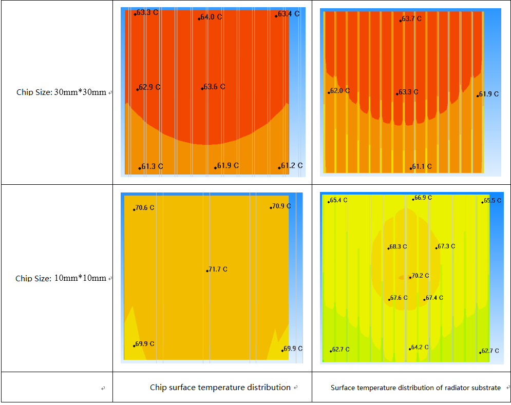
Under the two chip sizes, the heat flux density is:
30 mm * 30 mm:Pdens = 20 /30/30 = 0.022 W/mm2 = 2.22 W/cm2
10 mm * 10 mm: Pdens = 20/10/10 = 0.2 W/mm2 = 20 W/cm2
When the chip size was reduced, the heat flux density increased by 9 times.The heat sink caused a rise of about 8C in the chip without any changes.The thermal resistance of the heat sink increased from 2.18c /W to 2.59c /W, and the overall thermal resistance of the heat sink deteriorated by 19%.
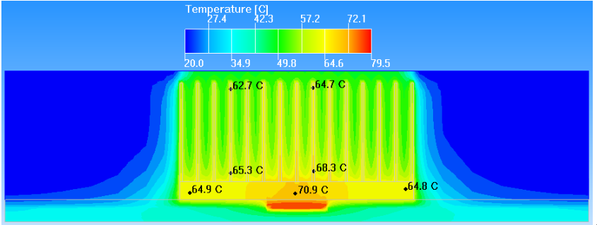
10mm*10mm Chip heat sink interface temperature distribution
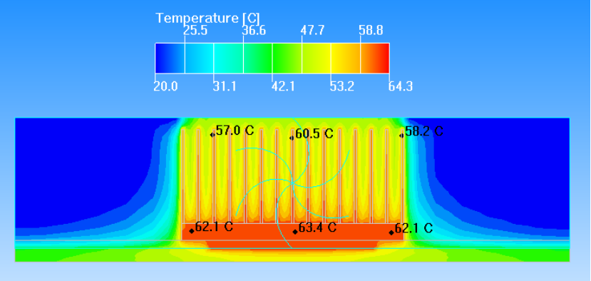
30mm*30mm Chip heat sink interface temperature distribution
Due to the existence of the spreading resistance, when the heat flux density of the chip is high, the temperature at the edge of the heat sink will be significantly lower than that at the chip.Reduced efficiency at the edge of the heat sink.
Conclusion: the effective thermal resistance of the same heat sink will increase when the heat flux density of the heating source increases.
For chips with high heat flux density, the common methods to reduce the spreading resistance are as follows:
1) Thicken the substrate of the heat sink to reduce the heat transfer resistance in the plane direction;
2) Use heat sink materials with higher thermal conductivity;
3) Heat pipes are buried on the heat sink substrate;
4) Use VC compound to heat sink substrate.